This article explained the setup and hold time slack for different timing paths in digital IC design, following the setup and hold time equations explanation in the last posts.

Credit: Cadence Design Systems
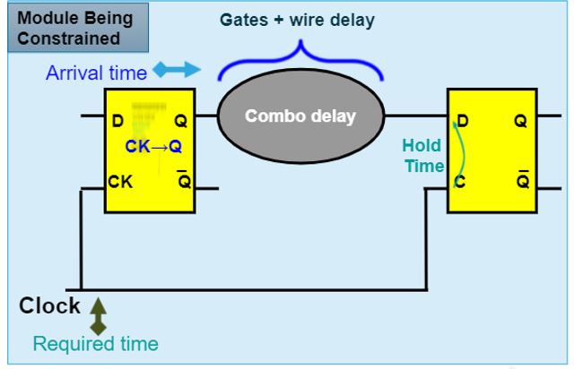
The figure above shows the most common timing path, register-to-register. The launching clock triggers the data into the first flip-flop and the capture clock captures the data, which saves the data into the receiving flip-flop. However, to reliably save the data into the flip-flop, the arrival time of the data required to meet the setup and hold time requirements of the flip-flop as explained in this post.
Setup and hold slack is defined as the difference between the required time (based on setup and hold time) and the arrival time of the data at the endpoint. The slack value is used by STA tools to identify the violated timing paths for further optimization to satisfy the setup and hold timing.
Setup Slack = Required Time - Arrival Time
Hold Slack = Arrival Time - Required Time
A positive slack shows that the timing path meets the timing constraint requirements (setup and hold), whereas a negative slack indicates the timing path violates the setup and hold timing constraints requiring further optimization.
Following are the different setup and hold slack equations for different timing paths
1. Register-to-Register Setup Slack

Credit: Cadence Design Systems
Arrival Time = Tck->q + Combo DelayRequired Time = Clock Period - Setup Time
Setup Slack = Required Time - Arrival Time
= Clock Period - Setup Time - Tck->q - Combo Delay
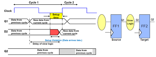
Following is an example of a negative setup slack. As the Combo Delay (Slow Logic) is too big, data D2 arrives late within the setup time window, which violates the setup time requirement.
Credit: Cadence Design Systems
2. Register-to-Register Hold Slack
Credit: Cadence Design Systems
Required Time = Hold TimeArrival Time = Tck->q + Combo Delay
Hold Slack = Arrival Time - Required Time
= Tck->q + Combo Delay - Hold Time
This indicates that the minimum total delay of the flip-flop CK-to-Q delay and Combo Delay required to be larger than the hold time constraint. This explained why the most common hold time fix is to add buffers between registers, which increases the combo delay for meeting hold time constraints.
3. Input-to-Register Setup Slack

Credit: Cadence Design Systems
Required Time = Clock Period - Setup Time (flip-flop R2)Arrival Time = Tck->q (R1) + Combo Delay 1 + Combo Delay 2
As Input Delay = Tck->q (R1) + Combo Delay 1, we have:
Arrival Time = Input Delay + Combo Delay 2
Setup Slack = Clock Period - Setup Time (R2) - Input Delay - Combo Delay 2
It is noted that Input Delay is an important timing constraint written in the SDC constraint file. This enables the synthesis/PNR tools to optimize the combo delay 2 to meet the setup time requirement.
4. Input-to-Register Hold Slack

Credit: Cadence Design Systems
Required Time = Hold Time (R2)Arrival Time = Input Delay + Combo Delay 2
Hold Slack = Input Delay + Combo Delay 2 - Hold Time (R2)
5. Register-to-Output Setup and Hold Slack

Credit: Cadence Design Systems
Setup Slack = Clock Period - Tck->q (R1) - Combo Delay 1 - External Delay External Delay (for setup slack) = Combo Delay 2 + Setup Time (R2)
Hold Slack = Tck->q (R1) + Combo Delay 1 + Combo Delay 2 - Hold Time (R2)
As External Delay (for hold slack) = Combo Delay 2 - Hold Time (R2), we have:
Hold Slack = Tck->q (R1) + Combo Delay 1 + External Delay
Note that External Delay is constrained in the SDC file.
Recommended Setup and Hold Time Tutorials:
Comments
Post a Comment