This article explained all the hold time equations for different timing paths in digital IC design.
Hold time is the minimum time duration that the input data required to be stable AFTER the active clock edge so that the input data can be reliably saved into the flip-flop. Read more about hold time: here.
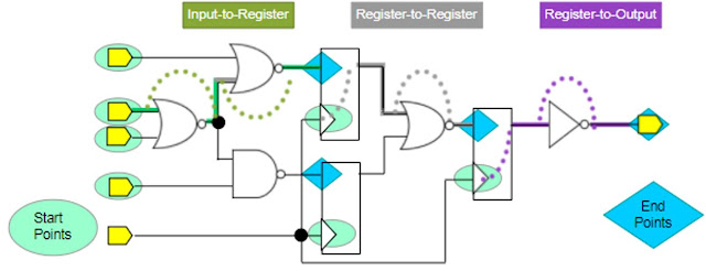
There are 3 main timing paths that require setup time constraints as described in the following figure: register-to-register, input-to-register, and register-to-output.
Credit: Cadence Design Systems
Hold Time Equation for Register-To-Register Timing Paths

Credit: Cadence Design Systems
Required Time = Hold Time (of the capturing flip-flop, from the timing .lib)
Arrival Time = CK→Q Delay (of Launching flip-flop) + Comb. Delay
To meet hold time constraints, Arrival Time ⋝ Required Time, meaning that data required to arrive (stable) at the next flip-flop after the hold time window.
=> CK→Q Delay (of Launching flip-flop) + Comb. Delay ⋝ Hold Time
=> Hold Time ≤ CK→Q Delay + Comb. Delay
This hold time equation implies that the minimum total of CK→Q Delay and Comb. Delay has to be large enough to meet the hold time constraint. This explained why the most common way for fixing hold time violation is buffer insertion, which adds more comb. delay for meeting the hold time equation.
Hold Time Equation for Input-To-Register Timing Paths

Credit: Cadence Design Systems
Required Time = Hold Time (of the capturing flip-flop R2, from the timing .lib)
Arrival Time = Input Delay (from SDC Constraint) + Comb. Delay 2
To satisfy the hold time check, Arrival Time ⋝ Required Time, meaning that data only changed outside of the hold time window after the active clock edge.
=> Input Delay + Comb. Delay 2 ⋝ Hold Time
=> Hold Time ≤ Input Delay + Comb. Delay 2
Hold Time Equation for Register-to-Output Timing Paths

Credit: Cadence Design Systems
Required Time = Hold Time (of the capturing flip-flop R2)
External Delay (From SDC Constraint) = Comb. delay 2 - Hold Time
=> Hold Time = Comb. Delay 2 - External Delay
Arrival Time = CK→Q Delay + Comb. Delay 1 + Comb. Delay 2
To meet the hold time requirement, Arrival Time ⋝ Required Time, meaning that data needed to reach the next flip-flop after the hold time duration.
=> CK→Q Delay + Comb. Delay 1 + Comb. Delay 2 ⋝ Hold Time
=> CK→Q Delay + Comb. Delay 1 + Comb. Delay 2 ⋝ Comb. Delay 2 - External Delay
=> CK→Q Delay + Comb. Delay 1 + External Delay ⋝ 0
To understand the setup time equations for different timing paths: check here
To understand the flip-flop schematic and operation, read here.
Read here to understand why setup and hold time are required in flip-flop
Comments
Post a Comment